Difference between revisions of "Evaluation of PMTs in High Magnetic Field"
(Created page with "'''Overview''' <br> The integration of the three Cherenkov detectors in the central detector involves setting their photo-sensor readouts in the non-uniform fringe field of th...") |
|||
| (8 intermediate revisions by the same user not shown) | |||
| Line 3: | Line 3: | ||
'''Test Facility at Jefferson Lab''' <br> | '''Test Facility at Jefferson Lab''' <br> | ||
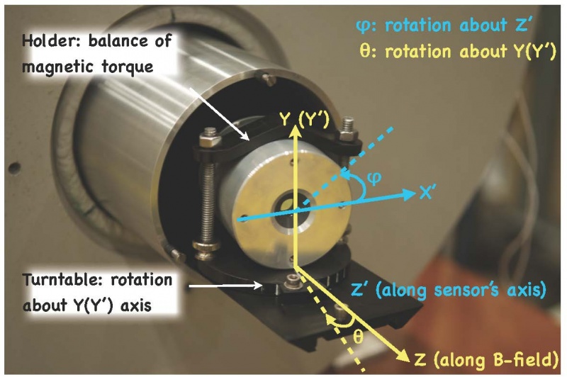
| + | The high-B sensor test facility was installed and commissioned during 2014-2015. Jefferson Lab allocated space specifically for this purpose in the new High Bay Test Building. The facility consists of a 5.1-T superconducting solenoid magnet, custom-designed dark test box, and electronics. Photographs of the test area, the dark box, and the magnet are shown below. | ||
| + | [[File:DarkBox_Photograph.jpg|800px|thumb|left|]] | ||
Latest revision as of 13:34, 27 January 2017
Overview
The integration of the three Cherenkov detectors in the central detector involves setting their photo-sensor readouts in the non-uniform fringe field of the solenoid. While an out-of-field readout option for the DIRC may be feasible, an in-field readout is the only option for the two RICH detectors. The objective of this activity, thus, has been to assess the gain and the timing performance of available photosensors in high magnetic fields (0T–5T) and for various relative orientations between the sensor and the magnetic field and to reasonably support (as needed for the R&D) further design optimization studies of these sensors. The long-term goal of the research is to recommend sensor options for Cherenkov-detectors readout in the magnetic field of the solenoid magnet.
Test Facility at Jefferson Lab
The high-B sensor test facility was installed and commissioned during 2014-2015. Jefferson Lab allocated space specifically for this purpose in the new High Bay Test Building. The facility consists of a 5.1-T superconducting solenoid magnet, custom-designed dark test box, and electronics. Photographs of the test area, the dark box, and the magnet are shown below.
